


Please Leave Us A Message

Haoyong Automotive Controls
A CPD Actuator converts electrical signals into mechanical movement through a controlled process involving an electric motor, transmission mechanism, and mechanical output system. When the actuator receives a command signal from a controller, the internal control unit processes the input and activates the motor. The motor then generates rotational force, which is transferred through gears or drive components and converted into linear or rotary movement. This movement allows the CPD Actuator to control valves, dampers, or other mechanical systems with accurate positioning and stable operation.
Understanding How a CPD Actuator Works
A CPD Actuator is an electromechanical device designed to transform electrical energy into physical movement. It is commonly used in industrial automation, HVAC systems, valve control applications, and various mechanical equipment where precise motion control is required.
Unlike manually operated mechanisms, a CPD Actuator receives electrical commands from a control system. These signals determine the direction, speed, and position of the actuator movement. This allows automated equipment to respond quickly to changing operating conditions.
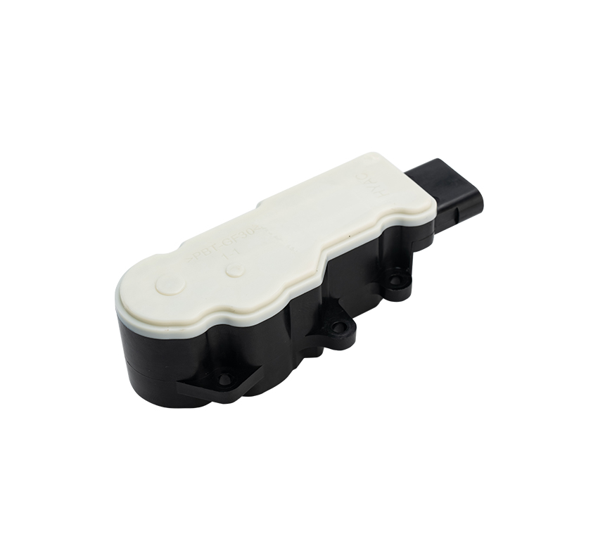
The working process usually starts when a control system sends an input signal to the actuator. The signal may come from a PLC, temperature controller, industrial automation system, or other electronic control devices. After receiving the signal, the actuator’s internal circuit analyzes the command and controls the motor operation.
The Process of Electrical Signal Conversion
The conversion process inside a CPD Actuator includes several important stages.
1. Signal Receiving and Processing
The first step is receiving an electrical input signal. The actuator controller identifies the required movement based on the received voltage, current, or digital command.
The control system determines whether the actuator needs to move forward, backward, open, close, or maintain a specific position. This electronic control process ensures that the actuator responds according to the required operation.
2. Motor Activation
After processing the signal, the internal controller supplies power to the motor. The motor converts electrical energy into rotational mechanical energy.
Depending on the design, a CPD Actuator may use different types of motors, including DC motors, AC motors, or stepper motors. The motor selection affects operating speed, torque output, and positioning accuracy.
3. Mechanical Transmission
The motor itself produces rotational movement, but many applications require controlled mechanical output. The transmission system inside the CPD Actuator converts and adjusts the motor rotation.
Gears, screws, belts, or other mechanical structures help increase torque, reduce speed, and transfer movement to the output shaft or rod.
This transmission system allows the actuator to generate enough force for operating valves, dampers, or industrial components.
4. Output Movement Control
The final stage is converting mechanical energy into usable movement. Depending on the actuator design, the output can be linear movement or rotary movement.
For example, a linear CPD Actuator moves a rod forward and backward, while a rotary actuator produces angular rotation. These movements are used to adjust mechanical parts according to system requirements.
Key Factors Affecting CPD Actuator Performance
Several factors influence how effectively a CPD Actuator converts electrical signals into movement.
The motor power determines the available force and operating capability. The transmission structure affects movement accuracy and mechanical efficiency. The control system influences positioning precision and response speed.
Environmental conditions such as temperature, humidity, vibration, and operating frequency can also affect actuator performance. Selecting the correct actuator model based on application requirements helps maintain stable operation.
Applications of CPD Actuators
CPD Actuators are widely used in industries that require automated movement control. Common applications include:
Industrial valve automation
HVAC airflow control systems
Manufacturing equipment
Process control systems
Robotics and automation equipment
Mechanical positioning systems
In these applications, the actuator helps reduce manual operation and improves system control.
Choosing a Reliable CPD Actuator Manufacturer
When selecting a CPD Actuator, buyers should consider product specifications, manufacturing capability, technical support, and customization options.
A professional CPD Actuator Manufacturer can provide different actuator models according to application requirements, including customized stroke length, torque, voltage, and control methods.
Working with an experienced CPD Actuator Supplier helps customers receive suitable products and technical guidance during selection and installation. A qualified CPD Actuator Factory usually has production equipment, testing procedures, and quality control systems to ensure consistent product performance.
A professional CPD Actuator Company can also provide solutions for different industries, helping customers integrate actuators into existing automation systems.
Conclusion
A CPD Actuator converts electrical signals into mechanical movement through signal processing, motor operation, mechanical transmission, and output control. This conversion process allows automated systems to achieve accurate and reliable motion control. With increasing demand for industrial automation, CPD Actuators continue to play an important role in improving equipment operation and system efficiency.

Mr. Hansol Kim